Home › Forums › Mastering STM32 book support forum › Tips on Developing USB apps using Nucleo Boards
- This topic has 0 replies, 1 voice, and was last updated 7 years, 1 month ago by
hkswan.
-
AuthorPosts
-
December 17, 2017 at 11:10 pm #8468
hkswan
Participant===============================================
Developing a USB app with a Nucleo64 board
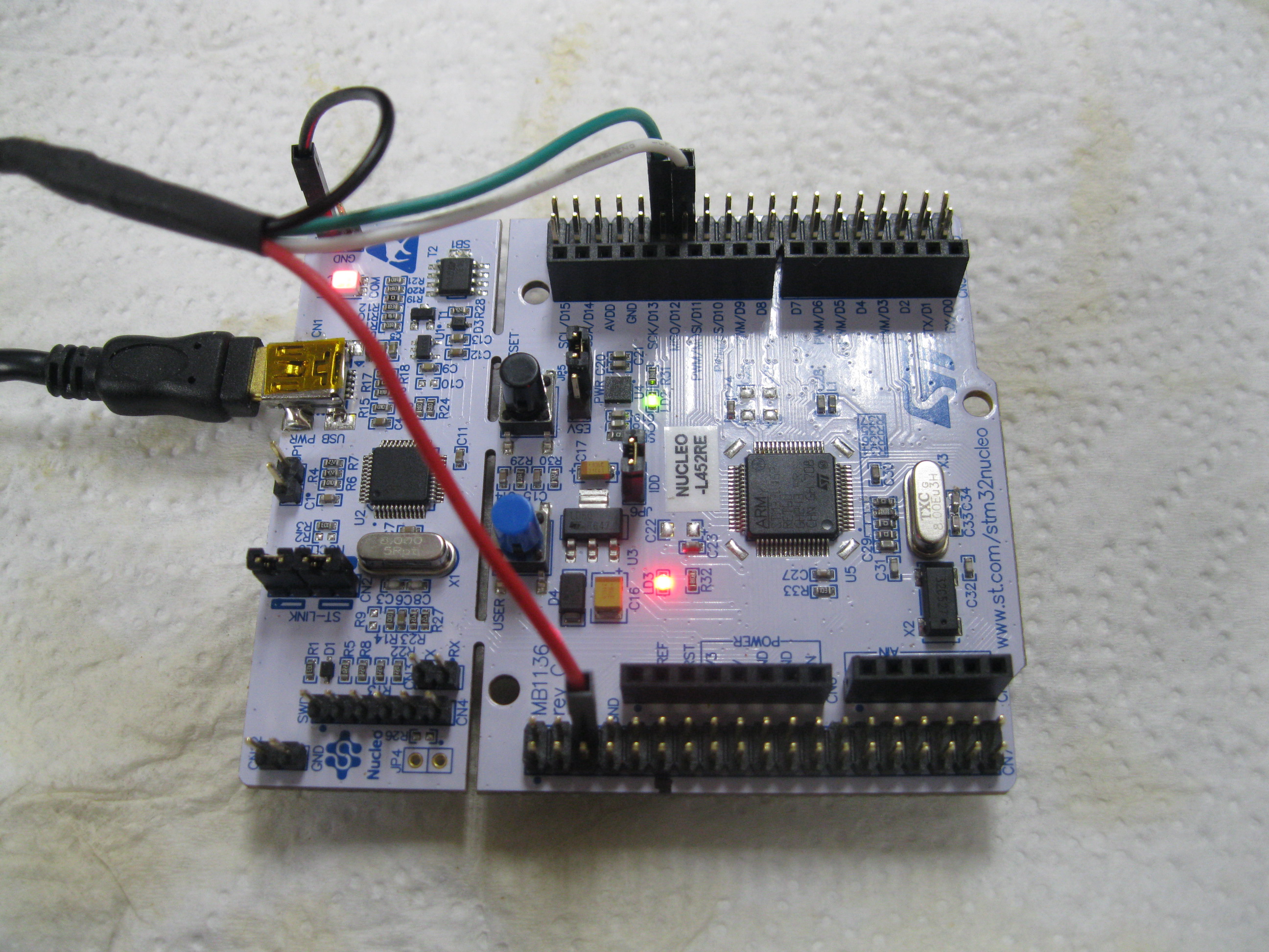
===============================================It has been said that developing a USB app with a Nucleo64 board is nearly impossible but this is not true. It can be done by constructing an appropriate USB Adaptor cable which attaches to a Nucleo64 board on 4 pins and appropriate selections in STM32CubeMX. The following was successfully performed with a Nucleo64 STM32L452 board using both the internal RC48 clock AND an external 8Mhz xtal.
===============================================
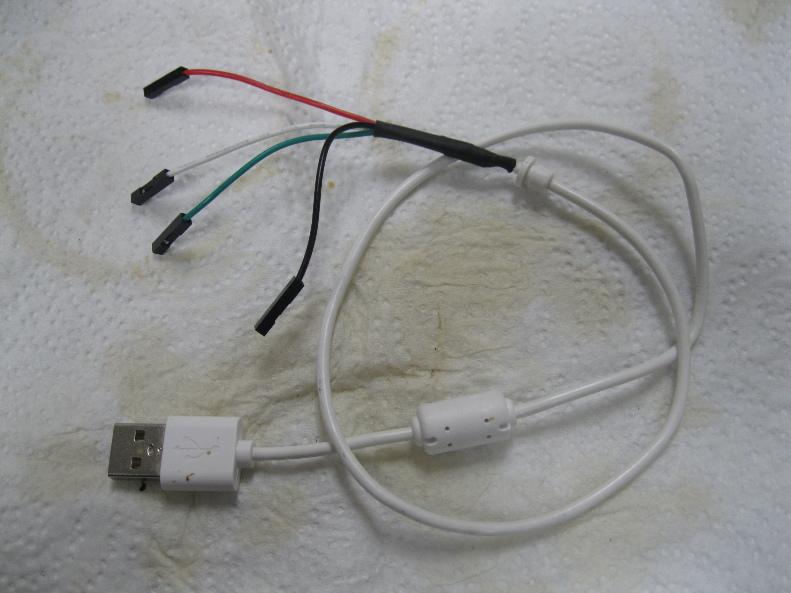
I. Fabricate a USB A to Nucleo64 USB Adaptor Cable as follows
===============================================——————————–
1.1 Reqired:
——————————–1 ea USB A TO PIGTAIL cable Digikey WM5091-ND or equivalent
4 ea Female to Female or Male to Female square post jumpers wires (1 each GREEN,WHITE,RED,BLACK)
4 ea 5/64 dia x about .25 inch Shrink Tubing,
1 ea 3/8 dia x about 1 inch Shrink Tubing——————————–
1.2 Fabrication Procedure:
——————————–1. Cut Jumpers in half, one of each color retaining a female of each color
2. Slip a 5/64 shrink tubing on each color
3. Strip then solder RED female half jumper to the USB RED pigtail wire
4. Slip shrink tubing over the joint and apply heat source to shrink.
5. Repeat 2,3,4 for the GREEN, WHITE and BLACK female half jumpers
6. Feed each half jumper through the 3/8 shrink tubing
7. Slide the 3/8 shrink down over the 4 soldered wires then apply heat source to shrink.===============================================
3.0 Power Options
===============================================1. Power via JP5-U5V allows debugging and power via ST-Link USB
2. Power via JP5-E5V allows operation power via the USB A to Nucleo64 USB Adaptor Cable===============================================
2.0 USB A to Nucleo64 USB Adaptor Cable Attachment
===============================================1 Connect USB power wire (red) to E5V pin on the Board (CN7 pin #6)
2 Connect USB ground wire (black) to any GND pin on the board (CN11,CN12 or CN10-)
3 Connect USB Data+ wire (green) to PA12 pin (CN10 pin #12) directly
4 Connect USB Data- wire (white) to PA11 pin (CN10 pin #14) directly===============================================
4.0 USB using Internal USB RC Clock
===============================================STM32CubeMX, In Pinout, USB, check enable
STM32CubeMX, In Pinout, USB_DEVICE, Select the appropriate class (I’m using Communications (CDC))
STM32CubeMX, In Clock Config, In Clock Config, in CLK48 Clock Select HSI48
STM32CubeMX, In Configuration, NVIC->NVIC Set USB event Interupt Preemption Priority to > 0 (I chose 3)
STM32CubeMX, In Configuration, NVIC->NVIC Set Timebase System Tick Timer Preemption Priority to 0 (highest)================================
3. Optional-External 8 Mhz Xtal clock
================================If you want to use an external 8Mhz crystal as your 48Mhz USB clock then you’ll have to add the crystal to the Nucleo board, 2 loading capacitors, 2 0R jumpers and remove 2 jumpers. The additional instructions are given below.
——————————–
3.1 Modify Nuculeo STM32L452 board as follows
——————————–1. Mount 8MHz xtal to X3
Digikey 887-1233-ND or equivilent
(see UM1724 user manual, 24th page, paragraph 6.7.1
URL: http://www.st.com/content/ccc/resource/technical/document/user_manual/98/2e/fa/4b/e0/82/43/b7/DM00105823.pdf/files/DM00105823.pdf/jcr:content/translations/en.DM00105823.pdf
2. Mount 18pf 0603 NPO caps to C33 and C34 as xtal load capacitors
Digikey 399-8842-1-ND or equivalent
3 Mount 0R 0603 Jumper Resistors to R35 and R37 to connect xtal to cpu
4 Remove 0R 0603 Jumper Resistors at SB54 and SB55 to disconnect CPU external clock source from CN7.
5 Verify 0R 0603 Jumper at SB50 are not present.——————————–
3.2 STM32CubeMX Configuration to use external xtal for USB clock.
——————————–STM32CubeMX, In Pinout, RCC Select High Speed Clock (HSE) to “Crystal/Ceramic Resonator”
STM32CubeMX, In Pinout, USB, check enable
STM32CubeMX, In Pinout, USB_DEVICE, Select the appropriate class (I’m using Communications (CDC))
STM32CubeMX, In Clock Config, in PLL Source Mux Select HSE
STM32CubeMX, In Clock Config, in PLLSAI1 set *N multiplier to 12
STM32CubeMX, In Clock Config, in CLK48 Clock Select PLLSAI1Q
STM32CubeMX, In Clock Config, in System Clock Mux select PLLCLK
STM32CubeMX, In Clock Config, in PLL set *N to 10 (40Mhz) for system clock.
STM32CubeMX, In Configuration, NVIC->NVIC Set USB event Interupt Preemption Priority to > 0 (I chose 3)
STM32CubeMX, In Configuration, NVIC->NVIC Set Timebase System Tick Timer Preemption PRiority to 0 (highest)-
This topic was modified 7 years, 1 month ago by
hkswan.
-
This topic was modified 7 years, 1 month ago by
hkswan.
-
This topic was modified 7 years, 1 month ago by
hkswan.
-
This topic was modified 7 years, 1 month ago by
hkswan.
Attachments:
You must be logged in to view attached files. -
This topic was modified 7 years, 1 month ago by
-
AuthorPosts
- You must be logged in to reply to this topic.


